Rocker switches, a common and important electronic control component, are named for their boat-like shape. These switches connect and disconnect circuits through the “swinging” motion of a lever, and are widely used in everything from household appliances to industrial equipment.
This article will delve into the working principles, types, installation methods, safety regulations, and selection guide for rocker switches, helping readers gain a comprehensive understanding of this important component.
Basic Principles and Structure of Rocker Switches
A rocker switch is an electrical switch that operates on the lever principle. Its core mechanism involves pressing one end of the switch to change the state of the internal contacts, thereby connecting or disconnecting the circuit.
When the user presses one end of the switch, the moving contact contacts or separates from the stationary contact, closing or opening the circuit. This design makes the switch operation simple and intuitive, with clear status indication.
A standard rocker switch consists of three main components: a housing (protecting the internal components), an actuator (the lever part for manual operation), and contacts/terminals (the metal parts that connect to the circuit).
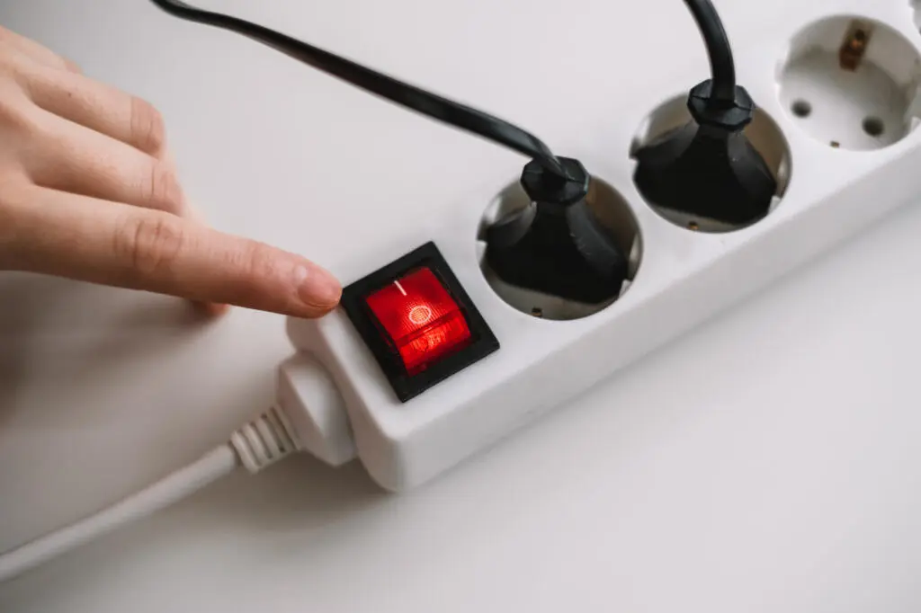
Most rocker switches have clearly marked “ON” and “OFF” positions, and some also have indicator lights (such as LEDs or bulbs) that illuminate when the switch is in the ON position, making it easier for users to identify the switch status in low-light conditions.
Main Types and Technical Parameters of Rocker Switches
Classification by Pole Position and Throw Method
Rocker switches can be classified into several types based on their internal structure and operating method, the most common being single-pole single-throw (SPST) and double-pole double-throw (DPDT).
Single-pole single-throw (SPST) is the most basic type of rocker switch, controlling only one circuit’s on/off state. It has two terminals: one for input voltage and the other for output voltage. When the switch is in the “ON” position, the circuit is closed, and current flows; when in the “OFF” position, the circuit is open, and current is blocked.
Single-pole double-throw (SPDT) switches have one moving contact and two stationary contacts, which can be used to connect the two stationary contacts separately. This type of switch allows users to select between two different circuits, enabling more complex control functions.
Double-pole double-throw (DPDT) switches are more complex, containing two moving contacts and four stationary contacts, providing four channels and allowing simultaneous control of two independent circuits. This type of switch is suitable for applications requiring simultaneous control of multiple circuits.

Classification by Special Functions
Besides the basic type, rocker switches can also be classified according to special functions, such as momentary switches (holding the state only while pressed, returning to the original position after release) and holding switches (remaining in the pressed position until operated again).
Waterproof rocker switches feature a special sealing design to prevent moisture and dust from entering the switch. For example, some series have an IP68 protection rating, allowing them to function normally even after immersion in 1 meter of water for more than 30 minutes. These switches employ a front-sealed design, with the button, base, and bracket all sealed, making them suitable for use in humid or dusty environments.
Shock-resistant rocker switches utilize a reinforced structural design and mounting methods to improve shock resistance. By increasing mechanical strength and stability, and using appropriate fixing bolts and brackets, the impact of vibration on switch performance is effectively reduced.
Illuminated rocker switches integrate an indicator light system, with light sources including incandescent lamps, neon lamps, or LEDs. Lighting methods can be divided into dependent (illuminates only in a specific location) and independent (always illuminated). Different colored indicator lights help users quickly identify the switch status and function across various devices.
Key Technical Parameters
Understanding the technical parameters of rocker switches is crucial for correct selection. Here are some key parameters:
- Rated Current/Voltage: The maximum current and voltage the switch can safely withstand, such as 6A/250VAC or 10A/28VDC.
- Electrical Life: The number of times the switch can reliably operate under normal use, typically ranging from 10,000 to 150,000 cycles.
- Contact Resistance: The resistance between contacts; generally, lower is better. High-quality switches can have contact resistance as low as 0.02mΩ.
- Insulation Resistance: An indicator of the switch’s insulation performance, typically exceeding 1000MΩ.
- Dielectric Strength: The highest voltage the switch can withstand without breakdown, such as 1500VAC.
- Operating Temperature Range: The temperature range within which the switch operates normally, such as -40°C to +85°C.
Rocker Switch Installation and Wiring Guide
Proper installation is crucial for ensuring the long-term stable operation of the rocker switch. The following are the basic installation steps and precautions:
Preparation Before Installation
Before starting installation, always disconnect the power supply to the relevant circuit to prevent electric shock. Prepare necessary tools, including screwdrivers, electrical tape, wire strippers, etc. Confirm that the switch specifications match the required specifications, including rated current, voltage, and physical dimensions.
Installation Steps
- Determine the Installation Location: Choose a location that is easy to access and will not interfere with other components. Use a template or measuring mark to mark the area to be cut.
- Make Mounting Holes: Drill holes or rectangular openings in the panel according to the switch dimensions. For example, some mini rocker switches require a panel opening size of 13.0mm × 12.9mm. Ensure the opening size is accurate to avoid the switch being too large and not securely fixed.
- Wiring: Connect the wires according to the circuit design. Switches typically have three terminals: a common terminal (COM), a normally open terminal (NO), and a normally closed terminal (NC). Single-pole switches generally have only two terminals.
You can use an appropriate wire gauge to make sure it can safely carry the expected current. Connection methods can include soldering, crimping, or screw mounting. - Secure the switch: Insert the switch into the mounting hole, snapping it in from the front of the panel. Many rocker switches use a snap-fit design to accommodate panels of different thicknesses. Ensure the switch is securely installed and not loose.
- Final check: Check that all wiring is correct and secure. After confirming everything is correct, restore power and test the switch’s functionality.
Wiring Precautions
Wire gauge selection is crucial. The wire cross-sectional area must be determined based on the switch’s rated current and the line length. A general principle is to use wire capable of handling at least twice the maximum load current, with a voltage drop not exceeding 3%.
Distinguishing Power Polarity: While most rocker switches are polarity-insensitive for AC, some low-voltage DC applications or switches with indicator lights require polarity differentiation. Confirm circuit design requirements before wiring.
For waterproof switches, ensure the sealing ring is correctly installed and not squeezed or damaged. Use waterproof connectors or sealant to treat cable entry points and maintain overall sealing.
Selection Considerations and Application Scenarios for Rocker Switches
Key Selection Factors
Choosing a suitable rocker switch requires comprehensive consideration of several factors:
Electrical parameters are the primary consideration, including the type of load the switch needs to control (resistive, inductive, capacitive, etc.), operating voltage, and current. For example, a 10A/250VAC switch can be selected for resistive loads, while a model capable of withstanding inrush currents is required for motor loads.
Environmental conditions directly affect switch performance and lifespan. Waterproof and dustproof switches (such as IP67 or IP68 ratings) should be selected for humid and dusty environments. Explosion-proof switches should be selected for locations with flammable materials or explosion risks. Switches made of high-temperature-resistant materials should be selected for high-temperature environments.
Mechanical requirements include the operating method (holding or instantaneous), lever size and shape, and operating force. Switches with moderate operating force and good feel should be selected for applications requiring frequent operation.
Safety certification is a crucial indicator of switch quality. Check if the switch has passed relevant safety certifications such as UL, CSA, and VDE. For example, the UL94 flame retardant rating is an important standard for measuring the flame retardant performance of materials.
Cost and availability should also be considered. While meeting technical requirements, choose products with high cost-effectiveness and stable supply.
Main Application Scenarios
Rocker switches are widely used in various fields:
Household appliances are the most common application area for rocker switches, such as televisions, audio equipment, and kitchen appliances. These applications typically choose switches with an aesthetically pleasing appearance and easy operation.
Industrial equipment includes machine tools, control systems, and power supply equipment. Industrial environments have higher requirements for the reliability, durability, and safety of switches, often selecting products with high rated current and high protection levels.
The automotive electronics field uses rocker switches to control systems such as headlights, wipers, and air conditioning. The automotive environment requires switches to withstand temperature changes, vibration, and electromagnetic interference.
Marine and aerospace applications have extremely high requirements for the fire resistance, corrosion resistance, and vibration resistance of switches. For example, rocker switches used in aerospace equipment must meet stringent flame-retardant standards.
Safety Specifications and Troubleshooting for Rocker Switches
Safety Standards and Specifications
Rocker switches must comply with various safety standards and specifications to ensure user safety and reliable equipment operation.
Flame-retardant standards, such as UL94, specify the flammability rating of plastic materials. Flame-retardant materials effectively inhibit the spread of fire and improve equipment safety. In fields with extremely high fire protection requirements, such as marine and aerospace applications, switches meeting the corresponding flame-retardant rating must be selected.
Protection ratings are indicated by IP codes, defining the level of protection against solid foreign objects and liquids. For example, IP67 indicates complete dust and short-term immersion protection, while IP68 indicates protection under continuous immersion conditions.
Electrical safety standards ensure that the switch operates safely under rated electrical parameters. Dielectric strength testing verifies that the switch can withstand transient overvoltages without breakdown.
Common Faults and Troubleshooting
Even high-quality rocker switches can fail. Here are some common problems and solutions:
Complete switch failure may be due to internal contact oxidation, loose or broken wiring. Inspect and rewire or replace the switch.
A deterioration in the feel of the switch is usually due to wear or contamination of the internal mechanism. For frequently used switches, consider replacing them with a more durable model.
If the indicator light is off but the switch functions normally, the indicator light may be faulty or there may be a problem with the related circuitry. Check the indicator light power supply, and wiring.
Overheating of the switch is often caused by overload or increased contact resistance. Check if the load current exceeds the rated value, and clean or replace the contacts.
Regular inspection and maintenance can extend the lifespan of the switch and ensure safe system operation. It is recommended to check the switch status regularly to identify and resolve potential problems promptly.
Conclusion
Rocker switches, as a simple yet crucial electrical control component, have a direct impact on the normal operation and safety of various electrical equipment when selected and used correctly. With technological advancements, rocker switches are developing towards higher performance, greater intelligence, and greater environmental friendliness.
The application of new materials and processes will further improve the electrical performance and mechanical lifespan of switches, meeting increasingly complex application requirements.
Whether you are a designer, installer, or end-user, a thorough understanding of the principles, characteristics, and application points of rocker switches will help improve the reliability and safety of your system.
In specific projects, the most suitable rocker switch product should be selected based on actual application requirements, taking into account electrical parameters, environmental conditions, safety standards, and economic factors.
