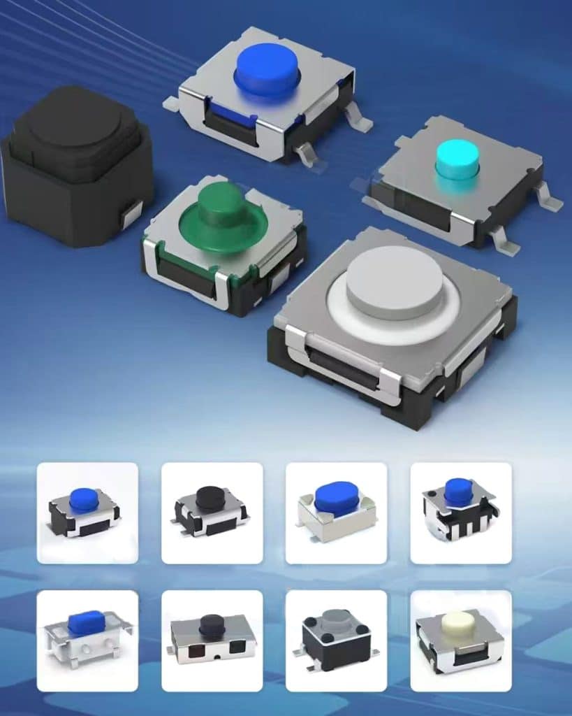
The Four-Terminal Enigma: A Deep Dive into the Design of Tactile Switches
In the intricate world of mechanical keyboards and electronic controls, the humble tactile switch is a fundamental component. To the casual observer, its function seems simple: press down to complete a circuit.
However, a closer inspection reveals a curious design choice: while many basic switches have only two terminals, a significant number, especially those designed for printed circuit board (PCB) mounting, feature four.
This apparent redundancy is not an oversight but a deliberate and clever engineering solution addressing critical needs in manufacturing, reliability, and versatility.
The core reason some tactile switches have four terminals is to enhance mechanical stability during soldering and to provide design flexibility for PCB layout. Crucially, only two of these terminals are electrically active (the “primary” pins); the additional two are non-electrical, serving purely as mechanical anchors.
This design ensures a robust connection to the PCB, prevents rocking during actuation, and allows the switch to be compatible with a wider range of PCB footprints, including those designed for different switch types.
To fully understand this, we must dissect the switch’s anatomy, explore the soldering process, and examine the historical context of PCB design.

Part 1: The Basic Two-Terminal Switch – How Simplicity Works
Before tackling four terminals, we must understand the fundamental principle of a two-terminal switch. A standard tactile momentary switch is a marvel of simple engineering. Its core components are:
- Housing: A plastic case that contains all internal components.
- Button/Plunger: The part the user presses.
- Metal Dome: A small, curved disc usually made of stainless steel. This is the heart of the “tactile” response. It provides the satisfying “click” or bump feeling when pressed.
- Contacts: Stationary electrical contacts on the base of the switch.
- Terminals (Pins): The metal legs that extend from the switch, allowing it to be soldered to a PCB.
In a two-terminal switch, the operation is straightforward:
- At Rest: The metal dome is curved upward, not touching the two fixed contacts on the base. The circuit between the two terminals is open (no electrical connection).
- When Pressed: The plunger pushes down on the center of the metal dome, causing it to buckle and snap downward. This action makes the center of the dome bridge the gap between the two fixed contacts. The circuit is now closed (electrical connection is made).
- When Released: The inherent spring force of the metal dome causes it to snap back to its original curved shape, breaking the connection with the contacts and returning the circuit to its open state.
This design is perfectly functional and is still used in millions of applications where extreme mechanical stability is not a primary concern, such as in remote controls or calculators where the switch is mounted directly onto a flexible membrane.
Part 2: The Limitations of Two-Terminal PCB Mounting
The problems with a simple two-terminal design become apparent when the switch is intended for mounting on a standard rigid PCB, especially in devices like mechanical keyboards that demand a high-quality, consistent user experience.
- Mechanical Instability (The “Rocking” Problem): A two-terminal switch is only anchored to the PCB at two points along a single axis. If you press the switch off-center (especially near the top or bottom), it can create a lever action, causing the switch to rock slightly. This rocking can feel cheap and imprecise. More critically, during the soldering process (specifically reflow soldering), this instability can be disastrous.
- Soldering Process Challenges – The “Tombston” Effect: In modern electronics manufacturing, a common soldering technique is reflow soldering. The entire populated PCB is passed through an oven where the solder paste melts (reflows) to form the electrical and mechanical bonds. During this process, components can experience uneven forces.
◦ Surface Tension Imbalance: If the solder on one terminal melts a fraction of a second before the other, the immense surface tension of the molten solder can pull on that terminal.
◦ The Result: With only two points of contact, this unbalanced force can literally lift the un-soldered end of the component upright, standing it on its one soldered terminal like a tombstone. This defect is aptly named the “tombstoning” or “drawbridging” effect, and it renders the component useless. - Limited PCB Layout Guidance: With only two pins, the switch has less physical registration with the PCB during the automated placement process before soldering. It’s easier for it to shift slightly out of alignment.
Part 3: The Ingenious Four-Terminal Solution – Strength and Flexibility
The four-terminal switch elegantly solves the problems inherent in the two-terminal design. It is essential to clarify that this is not a switch with two independent circuits. It is still a single-pole, single-throw (SPST) switch. The four terminals are arranged in two pairs.
- The Primary Terminals (Pins 1 and 2): These are the electrically active pins. They are connected to the internal contacts that are bridged by the metal dome. They are responsible for carrying the signal.
- The Secondary (or Dummy) Terminals (Pins A and B): These are the crucial addition. They are electrically isolated from the internal switching mechanism. They are made of the same metal as the primary pins but serve no electrical function. Their sole purpose is mechanical.
Let’s break down the specific advantages these extra pins provide:
- Enhanced Mechanical Stability:
The two secondary pins act as sturdy anchor points. By having four points of contact arranged in a rectangular pattern, the switch is firmly secured to the PCB. This completely eliminates the “rocking” sensation during use, providing a solid, high-quality feel that is essential for products like mechanical keyboards. The switch body is now resistant to forces from any direction.
- Prevention of Tombstoning:
During reflow soldering, the four-pin design provides a massive advantage. Even if the solder on one primary pin melts first, the surface tension is counteracted by the mechanical resistance of the two secondary pins on the opposite side. The switch is effectively “locked” in place.
The additional solder joints dramatically increase the force required to lift any corner of the switch, making tombstoning extremely unlikely. This significantly improves manufacturing yield and reliability.
- PCB Layout and Compatibility:
This is a subtle but critical advantage. The four-pin layout is not arbitrary; it is often designed to be compatible with different PCB footprints.
- Dual-Function Pads: The secondary pins are frequently placed at a standard spacing. This means the same four-pin switch can be used on a PCB that has plated through-holes for all four pins, or on a PCB that only has holes for the two primary electrical pins.
The secondary pins can simply hang over the edge of the PCB or be snipped off if not needed, offering no detriment. - Alps Compatibility: Historically, there were two main mechanical switch footprints in the keyboard world: Cherry MX and Alps SKCL/SKCM. The Alps-style switches used a wider pin spacing for their two electrical pins.
To allow keyboard designers to create a single PCB that could accept either type of switch (a huge benefit for custom keyboard enthusiasts and manufacturers), many modern tactile switches are designed with a four-pin layout that mimics the Alps footprint.
The two primary pins are at the standard Cherry MX spacing, while the two secondary pins are placed at the wider Alps spacing. This provides maximum versatility without requiring two completely different switch molds.
4. Automated Assembly Assistance:
The four-pin design helps with the “pick and place” machines that populate PCBs. The extra pins provide more precise location points, ensuring the switch is correctly oriented and seated before the soldering process begins, reducing the chance of misaligned components.
Part 4: A Comparative Analysis – Two Pins vs. Four Pins
The following table summarizes the key differences:
| Feature | Two-Pin Switch | Four-Pin Switch |
| Primary Function | Basic electrical switching. | Enhanced-stability electrical switching. |
| Mechanical StabilityHigher | Low. Prone to rocking if pressed off-center. | High. Extremely solid and stable on the PCB. |
| Soldering Reliability | Higher risk of tombstoning during reflow. | Very low risk of tombstoning. |
| PCB Compatibility | Limited to its own specific two-pin footprint. | High. Often compatible with multiple footprints (e.g., standard and Alps-style). |
| Typical Use Cases | Consumer devices with membrane mounting, low-cost applications where feel is not critical. | High-quality mechanical keyboards, industrial control panels, test equipment, any application requiring a robust, reliable tactile interface. |
| Cost & Complexity | Slightly lower per unit. | Slightly higher per unit, but can reduce overall manufacturing costs by improving yield. |

Part 5: Practical Implications for Enthusiasts
The four-pin design has a direct impact on the mechanical keyboard community, particularly in the realm of “hot-swap” keyboards.
- Hot-Swap Sockets: Hot-swap keyboards use special sockets soldered to the PCB that allow switches to be plugged in and removed without any soldering. These sockets typically only accommodate the two primary electrical pins.
- The Need to Clip: If you purchase a four-pin switch for a hot-swap board, you will almost certainly need to clip the two plastic secondary pins (the little plastic legs on the bottom of the switch housing) with a small pair of flush cutters. If the switch has metal secondary pins, these may also need to be clipped or will simply not be inserted into the socket. Failing to do this will prevent the switch from seating properly on the PCB.
- Plate-Mounted vs. PCB-Mounted: This leads to the common terminology:
◦ Plate-Mounted Switches (3-pin): These are switches that typically have only the two metal primary pins and a central plastic alignment pin. They are designed to be used with a metal or plastic plate that stabilizes the switch top. The plate provides the mechanical rigidity, making the secondary anchor pins unnecessary.
◦ PCB-Mounted Switches (5-pin): This is the more accurate term for a four-pin switch. It has the two primary metal pins, the two secondary metal anchor pins, and the central plastic alignment pin. These are designed to be mounted directly to a PCB without a plate, relying on their own pins for all stability.
Therefore, the “four-terminal” switch is the engineering ideal, but its full potential is only realized when the PCB is designed to receive all of its pins.
Conclusion: A Testament to Thoughtful Engineering
The presence of four terminals on a tactile switch is a perfect example of form following function in electronic component design.
What might initially appear to be redundancy is, in fact, a sophisticated response to real-world challenges in mass production and product quality. The two extra pins transform the switch from a simple electrical component into a robust electromechanical module.
They combat the physical forces of manufacturing, enhance the tactile experience for the end-user by eliminating unwanted movement, and provide engineers with greater flexibility in product design. This small, incremental innovation highlights how continuous refinement in even the most commonplace components is driven by the relentless pursuit of reliability, efficiency, and quality.
The next time you feel the satisfying, solid bump of a well-made keypress, remember that part of that experience is thanks to the silent, steadfast support of two humble, non-electrical pins.

